Laminated Bus Structures
 |
The two power distribution technologies are used in modern electronic equipment are wiring harnesses and bus bars (laminated bus structures).
Wiring harnesses are cost effective in low-volume, low-current
applications and typically provide adequate performance except in applications
where high capacitance, low impedance, electrical predictability, and dense
packaging are required.
Bus bars began to replace conventional wiring harnesses
in the early 1960's. Much more than just a rectangular conductor, the
modern bus bar is a precision electrically and mechanically-engineered passive
circuit component. |
Laminar bus | Planar bus | Epoxy bus | Need a Quote Now? Quote Request
| Advantages of Laminated bus bars versus conventional wire harnesses. |
- Reduced systems costs
- Minimum voltage drop
- Lower impedance
- Higher capacitance
- Denser packaging
- Reduced RFI, EMI, cross talk
|
- Direct mating with power supply, motherboards, etc.
- Improved reliability
- Easier installation
- Lower inductance
- Greater electronic noise filtering
- Wider choice of input/output methods
- Improved thermal characteristics
|
| There are a multitude of challenges caused
by increasing logic and memory circuit switching rates, shrinking space availability,
and demanding
noise, thermal, and reliability constraints. To help meet these challenges,
packaging designers have increased their use of bus structures in their designs
These structures are the standard method for the transfer of power in telecommunications,
electronic power conversion, motor drives, AC, DC or high frequency power
distribution and other related electronic applications.
Our laminated bus structures consist of several layers of electrically
conductive metal (usually copper), separated by insulating materials (Capton
for high temperature applications, and Mylar/Tevlor for lower temperature
applications). All conductors, insulation and terminations are laminated
under controlled heat and pressure into a single structure for the purpose
of making a connection between two or more points or circuits, whereas
a conventional bus bar uses only a single layer metal conductor. |
| Types of Bus Structures |
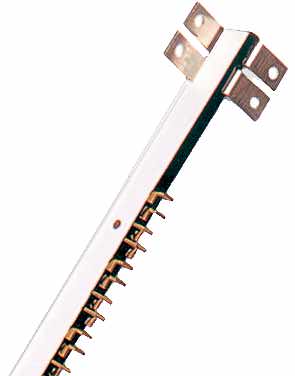 |
Laminar bus
Laminar bus consists of multiple copper and insulation layers which are
stacked and laminated then potted with insulation compound to completely
enclose the conductors. Single conductors can be close-molded with insulation.
Multiple terminations and multiple forms can be chosen. Laminar busses
are excellent for high current capacity and structural stiffness. |
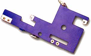
Planar bus
Planar bus uses multiple conductors laid side by side and then close-molded with insulation. Multiple terminations and multiple forms can be chosen. Planar busses are excellent for medium current capacity and permit multiple bends to fit compact spaces. |
 |
 |
Epoxy bus
Epoxy bus uses a single thick conductor which is insulated with an electrostatic
epoxy coating. Several can be mechanically assembled with value added hardware. These structures work
well with high current and will tolerate high temperatures. |
| To find out if your application can benefit from this technology please
e-mail us the following information and/or your drawings in IGES or DXF
format:
- Number of circuits
- Current required
- Number of returns desired
- Maximum voltage drop required
- Capacitance and inductance limits
- Minimum dielectric breakdown
- Number of terminations
- Space available
- Temperature
required
- Chemical resistance
- Regulatory UL / CSA / TUV
|
| Why is inductance a concern? |
|
| When using IGBT's, low inductance is a critical element for safe and
efficient operation. Stray inductance on the source-return path of the
DC bus from the DC capacitor bank to the inverter devices can cause:
- Reduced switching frequency. Parasitic oscillations may get out
of control and cause the inverter to exceed its safe operating area.
- Excessive transient overshoots in conventional hard switching converters
resulting in increased device heating, which eventually exceeds the
device's safe operating area causing device failure.
Typically, complex snubbers are used to reduce the destructive effects
of the bus inductance introduced when long interconnection distances are
used between switching devices to minimize the effects of heat generated
by the power devices.
Complex snubber circuits also add more components making the system more
costly and more difficult to manufacture. |
|
| Controlling Inductance |
|
Laminated bus structures help to control the two components of conductor
inductance which are, self inductance and mutual inductance.
Self inductance
In comparing a round conductor to a rectangular bus bar typically used
in laminated bus structures, the rectangular bar has 1/3 to 1/2 the self
inductance of a
round conductor of equal length and cross sectional area.
Mutual inductance
With a laminated structure mutual inductance reduction
occurs with bus bars configured in a side-by-side layout. This has less
effective inductance than wiring harnesses because of their shape and the
existence of some mutual cancellation along the conductor edges. The lowest
effective inductance occurs when a wide DC plus plate is placed directly
on top of a wide DC minus plate. This provides greater surface area for
flux cancellation, since conductors with opposite current polarity are
in close proximity to each other. The closer the conductors can be placed
to each other, the greater the mutual cancellation and decrease in effective
inductance. |
|
|


