Silicon Carbide Varistors - Zinc Oxide MOV’s

SiC Disk VaristorsSiC Rod and Tube VaristorsMOV / Zinc Oxide (ZnO) VaristorSilicon Carbide Varistors with LeadsSi-Metal Ceramic Composite Resistors ZnO Block Varistors
|
Our Silicon carbide varistors are made from about 90% silicon carbide of different grain sizes and 10% ceramic binder and additives. The raw material is formed into various varistors geometric dimensions and then sintered under specific atmospheric and ambient conditions at a high temperature.
A layer of brass is then flame sprayed on as an electrical contact. Other standard metallized contacts include Aluminum, Copper, Nickel and Silver. In the case of disks, an electrical connection is created by clamping a metal plate to each side of the disk using tie rod. Large assemblies in the case of disks are fashioned using metal plates with tab connections on each side of these disks to create series and parallel stacks of disks to provide appropriate overvoltage protection for high power. Smaller disks simply have tinned copper wires soldered to the brass layer and can be further processed to include a dielectric coating.
Geometries are manufactured to suite the electric values required by varying the OD, ID, thickness and length. Our manufacturing process yields good voltage dependences and high energy absorption.
Key features of Silicon Carbide Varistors
- Self-Healing.
- Used in Air/ Oil/ SF6 Environments.
- Configurable into Single or Modular Assemblies.
- Extremely High Ampacity.
- High Surge Energy Rating.
- 100% Active Material.
- Repeatable Non-Linear Characteristic.
- High Voltage Withstand.
- Essentially Non-Inductive.
Below is a list of our standard diameter disks 37, 45, 60, 80, 95, and 150mm: Energy absorption per disk ranges up to 122,290J allowing disk assemblies with extremely high energy absorption ratings in the tens of Mega-Joules.
Mechanical Parameters
Description |
Abbreviation |
Range |
Outside Diameter |
Do |
40 to 150 mm |
Inside Diameter |
Di |
10 to 30 mm |
Length |
L |
2 to 25 mm |
Disk Specifications
150mm Disks
| OD |
ID |
Thickness |
Continuous Operating
Voltage |
Max Power
Dissipation |
Max. Energy
Absorbtion |
Max. Pulse Current
(80/20us) |
Typical Production
Level |
Varistor
V/A |
Exponent |
| mm |
mm |
mm |
Vdc |
Vrms |
W |
J |
A |
Peak A |
Peak Avg A |
Vdc/Vac |
mAdc/mAac |
1/β |
| 150 |
21 |
7.6 |
250 |
227 |
45.2 |
48130 |
350 |
1000 |
50 |
405 to 495 |
1000 |
5 |
| 150 |
21 |
10 |
838 |
348 |
59.5 |
62940 |
160 |
1110 |
50 |
585 to 715 |
1000 |
5 |
| 150 |
21 |
12.7 |
400 |
440 |
75.6 |
79600 |
50 |
1200 |
50 |
810 to 990 |
1000 |
5 |
| 150 |
21 |
12.7 |
435 |
478 |
75.6 |
79600 |
100 |
1350 |
50 |
900 to 1100 |
1000 |
5 |
| 150 |
21 |
19 |
480 |
528 |
113.2 |
114780 |
150 |
1500 |
50 |
990 to 1210 |
1000 |
5 |
| 150 |
21 |
7.6 |
1 |
1 |
45.2 |
49680 |
15000 |
280 |
500 |
50 to 60 |
25000 |
3 |
| 150 |
21 |
7.6 |
21 |
19 |
45.2 |
49680 |
30000 |
700 |
500 |
150 to 200 |
25000 |
4 |
| 150 |
21 |
7.6 |
250 |
227 |
45.2 |
49680 |
350 |
1150 |
50 |
405 to 495 |
1000 |
5 |
| 150 |
21 |
7.6 |
275 |
250 |
45.2 |
49680 |
200 |
1500 |
50 |
250 |
15 to 45 |
5 |
| 150 |
21 |
10 |
18 |
17 |
59.5 |
65880 |
30000 |
440 |
500 |
50 to 70 |
25000 |
3 |
| 150 |
21 |
10 |
383 |
348 |
59.5 |
64960 |
160 |
1800 |
50 |
585 to 715 |
1000 |
5 |
| 150 |
21 |
12.7 |
27 |
24 |
75.6 |
82160 |
30000 |
950 |
500 |
200 to 250 |
25000 |
3 |
| 150 |
21 |
12.7 |
200 |
181 |
75.6 |
82160 |
500 |
1700 |
50 |
440 to 660 |
500 |
4 |
| 150 |
21 |
12.7 |
463 |
421 |
75.6 |
82160 |
100 |
2500 |
50 |
810 to 990 |
1000 |
5 |
| 150 |
21 |
12.7 |
602 |
547 |
75.6 |
82160 |
100 |
2750 |
50 |
900 to 1100 |
1000 |
5 |
| 150 |
21 |
15 |
2 |
2 |
89.3 |
98180 |
30000 |
500 |
500 |
80 to 120 |
25000 |
3 |
| 150 |
21 |
15 |
5 |
5 |
89.3 |
96810 |
10000 |
850 |
500 |
200 to 250 |
25000 |
3 |
| 150 |
21 |
15 |
9 |
8 |
89.3 |
96810 |
10000 |
1500 |
500 |
320 to 440 |
25000 |
3 |
| 150 |
21 |
15 |
11 |
10 |
89.3 |
96810 |
10000 |
1700 |
500 |
380 to 570 |
25000 |
3 |
| 150 |
21 |
15 |
13 |
12 |
89.3 |
96810 |
10000 |
2150 |
500 |
440 to 660 |
25000 |
3 |
| 150 |
21 |
19 |
331 |
301 |
113.2 |
122290 |
1000 |
2600 |
50 |
440 to 660 |
500 |
4 |
| 150 |
21 |
19 |
23 |
21 |
90.5 |
122290 |
10000 |
1800 |
500 |
855 to 1045 |
25000 |
3 |
| 150 |
21 |
19 |
662 |
602 |
113.2 |
122290 |
150 |
3400 |
50 |
990 to 1210 |
1000 |
4 |
| |
| 95mm Disks |
| OD |
ID |
Thickness |
Continuous Operating
Voltage |
Max Power
Dissipation |
Max. Energy
Absorbtion |
Max. Pulse Current
(80/20us) |
Typical Production
Level |
Varistor
V/A |
Exponent |
| mm |
mm |
mm |
Vdc |
Vrms |
W |
J |
A |
Peak A |
Peak Avg A |
Vdc/Vac |
mAdc/mAac |
1/β |
| 95 |
30 |
10 |
100 |
91 |
37.7 |
23340 |
5000 |
1050 |
200 |
100 |
100 to 200 |
3 |
| 95 |
30 |
10 |
120 |
109 |
37.7 |
23340 |
5000 |
1250 |
200 |
120 |
85 to 170 |
3 |
| 95 |
30 |
10 |
150 |
137 |
37.7 |
23340 |
5000 |
1450 |
200 |
150 |
65 to 130 |
3 |
| 95 |
30 |
10 |
180 |
164 |
37.7 |
23340 |
200 |
850 |
20 |
180 |
55 to 110 |
4 |
| 95 |
30 |
10 |
220 |
200 |
37.7 |
23340 |
200 |
1050 |
20 |
220 |
45 to 90 |
4 |
| 95 |
30 |
10 |
270 |
246 |
37.7 |
23340 |
200 |
1250 |
20 |
270 |
35 to 70 |
5 |
| 95 |
30 |
10 |
330 |
300 |
37.7 |
23340 |
200 |
1450 |
20 |
330 |
30 to 60 |
5 |
| 95 |
30 |
25 |
330 |
300 |
94.3 |
57660 |
1000 |
2200 |
20 |
330 |
30 to 60 |
3 |
| 95 |
30 |
25 |
390 |
355 |
94.3 |
57660 |
500 |
2500 |
20 |
3690 |
25 to 50 |
4 |
| 95 |
30 |
25 |
470 |
428 |
94.3 |
57660 |
500 |
2800 |
20 |
470 |
20 to 40 |
4 |
| 95 |
30 |
25 |
560 |
509 |
94.3 |
57660 |
50 |
3100 |
20 |
560 |
18 to 36 |
4 |
| 95 |
30 |
25 |
680 |
619 |
94.3 |
57660 |
50 |
3400 |
20 |
680 |
15 to 30 |
5 |
| 95 |
30 |
25 |
820 |
746 |
94.3 |
57660 |
50 |
3700 |
20 |
820 |
12 to 24 |
5 |
| 95 |
30 |
25 |
920 |
837 |
94.3 |
57660 |
50 |
4000 |
20 |
920 |
11 to 22 |
5 |
| |
| 80mm Disks |
| OD |
ID |
Thickness |
Continuous Operating
Voltage |
Max Power
Dissipation |
Max. Energy
Absorbtion |
Max. Pulse Current
(80/20us) |
Typical Production
Level |
Varistor
V/A |
Exponent |
| mm |
mm |
mm |
Vdc |
Vrms |
W |
J |
A |
Peak A |
Peak Avg A |
Vdc/Vac |
mAdc/mAac |
1/β |
| 80 |
20 |
7 |
232 |
211 |
22.1 |
9900 |
100 |
1100 |
10 |
220 |
4 to 12 |
5 |
| 80 |
20 |
10 |
18 |
16 |
31.5 |
16910 |
10000 |
390 |
100 |
24 |
340 to 450 |
3 |
| 80 |
20 |
10 |
94 |
85 |
31.5 |
16910 |
10000 |
850 |
100 |
50 |
20 to 40 |
3 |
| 80 |
20 |
10 |
80 |
73 |
31.5 |
16910 |
1000 |
340 |
10 |
80 |
20 to 40 |
4 |
| 80 |
20 |
10 |
150 |
137 |
31.5 |
16910 |
1000 |
630 |
10 |
150 |
20 to 40 |
4 |
| 80 |
20 |
10 |
170 |
155 |
31.5 |
16910 |
1000 |
850 |
10 |
200 |
35 to 70 |
4 |
| 80 |
20 |
10 |
220 |
200 |
31.5 |
16910 |
1000 |
1050 |
10 |
220 |
24 to 36 |
4 |
| 80 |
20 |
10 |
275 |
250 |
31.5 |
16910 |
100 |
1400 |
10 |
250 |
15 to 30 |
4 |
| 80 |
20 |
10 |
308 |
280 |
31.5 |
16910 |
100 |
1400 |
10 |
365 |
30 to 50 |
5 |
| 80 |
20 |
10 |
400 |
364 |
31.5 |
16910 |
100 |
1700 |
10 |
400 |
12 to 24 |
5 |
| 80 |
20 |
10 |
400 |
364 |
31.5 |
16910 |
100 |
1500 |
10 |
500 |
30 to 50 |
5 |
| 80 |
20 |
10 |
350 |
319 |
31.5 |
16910 |
100 |
1400 |
10 |
500 |
50 to 100 |
5 |
| 80 |
20 |
10 |
580 |
528 |
31.5 |
16910 |
100 |
2200 |
10 |
600 |
10 to 20 |
5 |
| 80 |
20 |
10 |
700 |
637 |
31.5 |
16910 |
10 |
3400 |
100 |
700 |
10 to 20 |
5 |
| 80 |
20 |
10 |
700 |
637 |
31.5 |
16910 |
10 |
3900 |
100 |
700 |
10 to 20 |
5 |
| 80 |
20 |
20 |
28 |
26 |
62.2 |
32990 |
15000 |
900 |
100 |
50 |
150 to 300 |
3 |
| 80 |
20 |
20 |
28 |
25 |
62.2 |
32990 |
15000 |
1500 |
100 |
75 |
50 to 100 |
3 |
|
| 60mm Disks |
| OD |
ID |
Thickness |
Continuous Operating
Voltage |
Max Power
Dissipation |
Max. Energy
Absorbtion |
Max. Pulse Current
(80/20us) |
Typical Production
Level |
Varistor
V/A |
Exponent |
| mm |
mm |
mm |
Vdc |
Vrms |
W |
J |
A |
Peak A |
Peak Avg A |
Vdc/Vac |
mAdc/mAac |
1/β |
| 60 |
10 |
2 |
24 |
22 |
3.7 |
990 |
100 |
135 |
5 |
36 to 54 |
100 |
4 |
| 60 |
10 |
2 |
27 |
25 |
3.7 |
990 |
100 |
180 |
5 |
28 to 42 |
10 |
4 |
| 60 |
10 |
2 |
33 |
30 |
3.9 |
1020 |
100 |
230 |
5 |
36 to 54 |
10 |
4 |
| 60 |
10 |
2 |
38 |
35 |
3.9 |
1020 |
100 |
260 |
5 |
44 to 66 |
10 |
5 |
| 60 |
10 |
2 |
49 |
45 |
3.9 |
1020 |
100 |
310 |
5 |
55 to 81 |
10 |
5 |
| 60 |
10 |
2 |
66 |
60 |
3.9 |
1020 |
100 |
390 |
5 |
76 to 114 |
10 |
5 |
| 60 |
10 |
4 |
82 |
75 |
5.8 |
1480 |
100 |
490 |
5 |
100 to 150 |
10 |
5 |
| 60 |
10 |
4 |
104 |
95 |
5.8 |
1480 |
90 |
620 |
5 |
128 to 192 |
10 |
6 |
| 60 |
10 |
4 |
115 |
105 |
5.9 |
1520 |
70 |
710 |
5 |
144 to 216 |
10 |
6 |
| 60 |
10 |
4 |
132 |
120 |
5.9 |
1520 |
50 |
820 |
5 |
176 to 264 |
10 |
6 |
| 60 |
10 |
5 |
154 |
140 |
5.9 |
1520 |
40 |
930 |
5 |
200 to 300 |
10 |
6 |
| 60 |
10 |
5 |
176 |
160 |
5.9 |
1520 |
30 |
1050 |
5 |
240 to 360 |
10 |
6 |
| 60 |
10 |
7 |
220 |
200 |
6.6 |
1670 |
20 |
1300 |
5 |
208 to 312 |
1 |
6 |
| 60 |
10 |
7 |
264 |
240 |
6.6 |
1670 |
12 |
1600 |
5 |
256 to 384 |
1 |
6 |
| 60 |
10 |
7 |
297 |
270 |
9.9 |
2470 |
8 |
1800 |
5 |
320 to 480 |
1 |
7 |
| 60 |
10 |
7 |
396 |
360 |
9.9 |
2470 |
4 |
1750 |
2 |
440 to 660 |
1 |
7 |
| 60 |
10 |
7 |
420 |
380 |
9.9 |
2470 |
2.5 |
1900 |
2 |
480 to 720 |
1 |
7 |
|
| 45mm Disks |
| OD |
ID |
Thickness |
Continuous Operating
Voltage |
Max Power
Dissipation |
Max. Energy
Absorbtion |
Max. Pulse Current
(80/20us) |
Typical Production
Level |
Varistor
V/A |
Exponent |
| mm |
mm |
mm |
Vdc |
Vrms |
W |
J |
A |
Peak A |
Peak Avg A |
Vdc/Vac |
mAdc/mAac |
1/β |
| 45 |
15 |
3 |
21 |
19 |
5.3 |
1600 |
100 |
115 |
5 |
56 |
85 to 170 |
3 |
| 45 |
15 |
3 |
25 |
23 |
5.3 |
1600 |
100 |
145 |
5 |
68 |
70 to 140 |
3 |
| 45 |
15 |
3 |
47 |
42 |
5.3 |
1600 |
100 |
180 |
5 |
68 |
60 to 120 |
3 |
| 45 |
15 |
6 |
68 |
62 |
10.7 |
3100 |
100 |
280 |
5 |
68 |
61 to 120 |
3 |
| 45 |
15 |
6 |
82 |
75 |
10.7 |
3100 |
100 |
340 |
5 |
82 |
50 to 100 |
3 |
| 45 |
15 |
6 |
100 |
91 |
10.7 |
3100 |
100 |
470 |
5 |
100 |
40 to 80 |
4 |
| 45 |
15 |
6 |
120 |
109 |
10.7 |
3100 |
100 |
560 |
5 |
120 |
30 to 60 |
4 |
| 45 |
15 |
6 |
150 |
137 |
10.7 |
3100 |
100 |
690 |
5 |
150 |
25 to 50 |
4 |
| 45 |
15 |
6 |
180 |
164 |
10.7 |
3100 |
100 |
820 |
5 |
180 |
22 to 45 |
4 |
| 45 |
15 |
6 |
330 |
300 |
10.7 |
3100 |
50 |
1600 |
2 |
330 |
12 to 24 |
4 |
| 45 |
15 |
15 |
180 |
164 |
26.8 |
7640 |
100 |
1000 |
5 |
180 |
22 to 45 |
3 |
| 45 |
15 |
15 |
220 |
200 |
26.8 |
7640 |
100 |
1250 |
5 |
220 |
18 to36 |
3 |
| 45 |
15 |
15 |
270 |
246 |
26.8 |
7640 |
50 |
1500 |
5 |
270 |
15 to30 |
3 |
| 45 |
15 |
15 |
330 |
300 |
26.8 |
7640 |
50 |
1750 |
5 |
330 |
12 to 24 |
4 |
| 45 |
15 |
15 |
390 |
355 |
26.8 |
7640 |
50 |
2150 |
5 |
390 |
10 to 20 |
4 |
| 45 |
15 |
15 |
470 |
428 |
26.8 |
7640 |
50 |
2400 |
5 |
470 |
8.5 to 17 |
4 |
|
| 37mm Disks |
| OD |
ID |
Thickness |
Continuous Operating
Voltage |
Max Power
Dissipation |
Max. Energy
Absorbtion |
Max. Pulse Current
(80/20us) |
Typical Production
Level |
Varistor
V/A |
Exponent |
| mm |
mm |
mm |
Vdc |
Vrms |
W |
J |
A |
Peak A |
Peak Avg A |
Vdc/Vac |
mAdc/mAac |
1/β |
| 37 |
10.5 |
2 |
26 |
24 |
5.6 |
2080 |
200 |
190 |
10 |
36 to 54 |
100 |
4 |
| 37 |
10.5 |
2 |
33 |
30 |
5.6 |
2080 |
200 |
220 |
10 |
28 to 42 |
10 |
4 |
| 37 |
10.5 |
2 |
38 |
35 |
6.3 |
2320 |
200 |
260 |
10 |
36 to 54 |
10 |
4 |
| 37 |
10.5 |
2 |
49 |
45 |
6.3 |
2320 |
200 |
310 |
10 |
44 to 66 |
10 |
5 |
| 37 |
10.5 |
2 |
55 |
50 |
6.3 |
2320 |
200 |
370 |
10 |
55 to 81 |
10 |
5 |
| 37 |
10.5 |
4 |
77 |
70 |
6.3 |
2320 |
200 |
460 |
10 |
76 to 114 |
10 |
5 |
| 37 |
10.5 |
4 |
93 |
85 |
9.2 |
3280 |
150 |
650 |
10 |
100 to 150 |
10 |
5 |
| 37 |
10.5 |
4 |
115 |
105 |
9.2 |
3280 |
100 |
790 |
10 |
128 to 192 |
10 |
6 |
| 37 |
10.5 |
4 |
121 |
110 |
9.2 |
3280 |
80 |
920 |
10 |
144 to 216 |
10 |
6 |
| 37 |
10.5 |
5 |
143 |
130 |
9.2 |
3280 |
60 |
1050 |
10 |
176 to 264 |
10 |
6 |
| 37 |
10.5 |
5 |
165 |
150 |
9.2 |
3280 |
40 |
1250 |
10 |
200 to 300 |
10 |
6 |
| 37 |
10.5 |
5 |
198 |
180 |
9.9 |
3520 |
30 |
1450 |
10 |
240 to 360 |
10 |
6 |
| 37 |
10.5 |
7 |
231 |
210 |
9.9 |
3520 |
20 |
1700 |
10 |
208 to 312 |
1 |
6 |
| 37 |
10.5 |
7 |
275 |
250 |
9.9 |
3520 |
15 |
1800 |
10 |
256 to 384 |
1 |
6 |
| 37 |
10.5 |
7 |
330 |
300 |
9.9 |
3520 |
8 |
1800 |
5 |
320 to 480 |
1 |
7 |
| 37 |
10.5 |
7 |
430 |
390 |
11.3 |
4000 |
4 |
1800 |
2 |
440 to 660 |
1 |
7 |
| 37 |
10.5 |
7 |
460 |
420 |
11.3 |
4000 |
2 |
2000 |
2 |
480 to 720 |
1 |
7 |
Electrical Parameters
| Item |
Range |
| Operating Temperature Range |
-40 to 150°C |
| TCV (Typical Temperature Coefficient of Voltage) |
-0.12 to 0.18 %/°C |
| TCI (Typical Temperature Coefficient Current) |
0.5 to 0.8 %/°C |
| Specific Heat Capacity Approximately |
2 J/cm³/°C |
| Thermal Conductivity |
0.07 W/cm² . °C/cm |
| Inductance |
nH’s (non-inductive) |
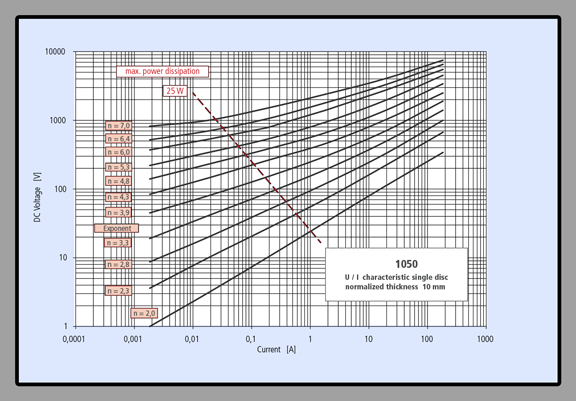
Disk U/I Characteristic Curves
|
Shielding Effect of Magnetic Field at 50Hz

Thickness of grain-oriented Si (Silicon) steel in the above chart corresponds to one layer of M6 or approximately three layers of M4. For toroidal transformer magnetic shielding is applied to the OD of the transformer. When Si steel is used it is the same as the transformer core material. M6, which is 0.35 mm thick, or M4 which is 0.27 mm thick (3 layers are applied), which equals 0.81mm approximating 0.7mm in the above chart.
Shielding effect of DC magnetic field

Applications
Nanocrystalline Magnetic Shielding has an extremely good weight to noise suppression ratio, making it an excellent choice to mitigate the magnetic noise generated from inductors in electronic devices, which are easily affected by magnetic fields or fluctuating magnetic fields. It is also used for magnetic shielding of buildings adjacent to power lines or power distribution installations.
Halogen-free noise suppression sheet with flame retardance composed of high performance nanocrystalline soft magnetic material. The nanocrystalline material is powered and bonded together with resin and formed into sheets. These sheets have high suppression effect on radiation noise and feature excellent complex relative permeability, resulting in high suppression of radiation noise in the range from 0.1 to 10 GHz.

Sheets are flexible and easy to handle, punch and cut in various shapes. They can even be applied to curved surfaces.
Applications
Highly effective in suppression of radiation noise and cross-talk noise in multilayered circuit boards in various electronic devices, flexible flat cables or on the internal or external surface of a chassis containing digital devices.
Specifications
Shape |
A4 Sheet |
Rolls |
Size (mm) |
210mm x 297mm |
300 mm x 20m |
330 mm x 20m |
Thickness |
0.13 mm |
0.25 mm |
0.50 mm |
0.13 mm |
0.25 mm |
0.50 mm |
Product code |
F1AH0946 |
F1AH0948 |
F1AH0950 |
F1AH0943 |
F1AH0944 |
F1AH0945 |
P/N |
K-EK013
210-297-T0 |
K-EK025
210-297-T0 |
K-EK050
210-297-T0 |
K-EK013
300-20M-T0 |
K-EK025
300-20M-T0 |
K-EK050
300-20M-T0 |
Density (103kg/m3) |
3.5 x 10³kg/m3 |
Complex relative
permeability (at 1GHz) µr'' |
8 |
Complex relative
permeability (at 1GHz) µr'' |
12 |
Tensile strength (MPa) |
1.5 Mpa |
Surface resistivity |
1 X 10⁹ Ωm |
Flame retardance |
V-0 |
Operating temperature |
-40 to +85 ℃ |
Thin 0.05 to 0.1mm flexible ferrite EMI suppressor sheets are polymer sheets filled with soft magnetic materials, which offer the highest magnetic permeability of 185µ' at 3MHz and applicable frequency range 100MHz to 6GHz. These are offered in standard roll widths of 210mm x 297mm and come in Halogen Free versions.
Type |
NS-HD |
NS-H |
NS-L |
NS-B |
NS-K |
NS-J |
NS-S |
NS-G |
Permeability
( at 3MHz) |
25 |
30 |
45 |
70 |
100 |
130 |
150 |
180 |
Applicable Frequency |
500MHz ~ 6GHz |
300MHz ~ 6GHz |
100MHz ~ 6GHz |
100MHz ~ 6GHz |
Operating Temperature ℃ |
-25 ~ +105 |
Standard Thickness (mm) |
0.05 ~ 0.1 |
Standard Size |
210mm x 297mm, roll type available |
Volume Resistivity (Ω•cm) |
1 x 10⁸ |
Remarks
|
High Freq. Low Freq. |
|
|
|
|
|
Low Freq. |
Halogen Free available. |

High frequency noise suppressing thin flexible polymer sheets filled with soft magnetic materials. Permeability at 3MHz ranges from 20µ’ to 50µ’ and appliable frequency range 100MHz to 3GHz. Standard thickness of 0.05 to 0.1mm which are offered in standard roll widths of 210mm x 297mm.
These also come in Halogen Free versions.
Type |
NS - F |
NS - FA |
NS - FAL |
NS - FR |
Permeability ( at 3MHz) |
20 |
20 |
50 |
50 |
Applicable Frequency |
100MHz ~ 3GHz |
Use Temp ℃ |
-25 to +85 ℃ |
Standard Thickness (mm) |
0.05 ~ 0.1 |
Standard Size |
210mm x 297mm, roll type available |
Volume Resistivity (Ω•cm) |
1 x 10¹² |
Remarks |
o Thin type of high
frequency noise.
o Halogen Free available. |
o Function of noise
absorbing and shielding
o Halogen Free available. |
o Thin type of low
frequency noise.
o 1000mmx200M. |
A series of flexible soft magnetic materials, which are designed to enhance communication distance of NFC systems and to improve power transfer efficiency of wireless power charging systems.
Permeability at 13.56MHz ranges from 25µ’ to 55 µ’ with thickness of 0.1 to 1.0mm. Standard rolls are 210mm wide with lengths up to 15 meters.
Type |
Permeability at 13.56MHz |
Thickness |
Standard size |
Frequency |
|
μ' |
μ'' |
(mm) |
(mm) |
|
RF-B |
55 |
1.0 to 1.5 |
0.1 to 0.5 |
210x297 |
13.56MHz |
RF-L |
45 |
1.5 to 2.0 |
0.2 to 1.0 |
210x297 |
RF-H |
25 |
1.0 to 1.5 |
0.2 to 1.0 |
210x15M |
Typical applications for RF Induction Sheets are used to increase communication distance of NFC systems (near field communication) or to enhance power transfer efficiency of WPCs (wireless power chargers).

Thin 0.05 to 0.1mm flexible ferrite EMI suppressor sheets are polymer sheets filled with soft magnetic materials, which offer the highest magnetic permeability of 185µ' at 3MHz and applicable frequency range 100MHz to 6GHz. These are offered in standard roll widths of 210mm x 297mm and come in Halogen Free versions.
Type |
MA-C |
MA-X |
MA-K |
MA-W |
Frequency |
4-6GHz |
8-13GHz |
21-26GHz |
75-110GHz |
Attenuation |
-20dB |
-20dB |
-20dB |
-5dB |
Type |
Resonant |
Broadband |
Operating Temperature |
-50 to 150 ℃ |
Thickness |
1.5 to 3.0 mm |
Standard Size |
300x300 mm |
These can be used for Electronic Toll Collection to improve ETC communication environments (5.8 GHz), reduce RCS of military vessels (8-12 GHz) or for Collaboration Detection and Prevention Systems, to reduce internal (cavity) resonance by isolating antennas from ground plane reflections (24, 77 GHz).

|